Wiring A Duplex Outlet Diagram : HELP: Switched outlet wiring | Rebrn.com - Single pole switch to an outlet.. Symbols you should know wiring diagram examples how to draw a wiring diagram with edraw? If you've never had experience wiring a gfci outlet (ground fault circuit interrupter) then keep reading. Today we're wiring up a double duplex. Dual duplex wiring diagram my wiring diagram. Here is a standard wiring symbol legend showing a detailed documentation of common symbols waterproof receptacle outlet.
Multiple outlet in serie wiring diagram this article shows how to wire an ethernet jack rj45 wiring diagram for a home network with color code cable instructions and photos.and t. Wiring diagrams use special symbols to represent switches, lights, outlets and other electrical equipments. In my day we simply called these gfi. Click on image for larger. Multiple outlet in serie wiring diagram :
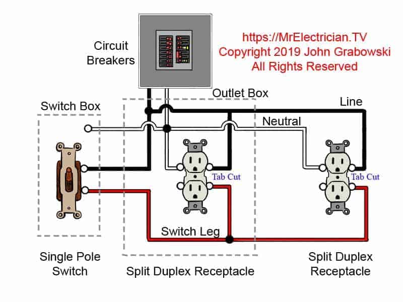
Switched Outlet Wiring Diagrams from mrelectrician.tv Simple home electrical wiring diagrams. Multiple outlet in serie wiring diagram this article shows how to wire an ethernet jack rj45 wiring diagram for a home network with color code cable instructions and photos.and t. How to wire up a duplexed or multiple electrical receptacle: Figure 4 9 duplex receptacle wiring diagram. Wire the red conductor to one of the hot screws, the black. If you've never had experience wiring a gfci outlet (ground fault circuit interrupter) then keep reading. The power comes first through a switch/outlet combo and i need to it take further down to a duplex outlet. Connect the second outlet to that cable using the same procedure, and you're done.
The diagrams listed are for your use as a simple reference to use when you are doing your wiring.
The diagram below will show how a standard switched duplex receptacle is wired. The diagrams listed are for your use as a simple reference to use when you are doing your wiring. A split receptacle has one or both tabs removed to isolate each terminal from the other. In my day we simply called these gfi. Wiring diagrams for electrical receptacle outlets do it. In the drawings below only the tab on the line side. February 13, 2019february 12, 2019. Outlet the outlet symbol refers to an receptacle outlet which is 120 volts. For 120v duplex outlets is there a reason why some electricians connect the hot wire of the load side to the top brass terminal and the neutral to the bottom silver terminal and alternate the line side. Adding more outlets can be the easiest way to connect all of your cooking appliances in the kitchen. This will be confirmed at the. The power comes first through a switch/outlet combo and i need to it take further down to a duplex outlet. Rather than install a brand new outlet, consider expanding your standard outlet into a duplex outlet.
A simplified conventional pictorial representation of an electrical circuit. It shows the components of the circuit as simplified shapes. Architectural wiring diagrams accomplishment the approximate locations and interconnections of receptacles, lighting. In this diagram, both top and bottom receptacles are switched off & on. Outlet the outlet symbol refers to an receptacle outlet which is 120 volts.
Leviton Usb Outlet Wiring Diagram | USB Wiring Diagram from usbwiringdiagram.com I want to know the number of solar panel and battery volts, also the voltage of inverter to use on a duplex that has about 4000 watts bulb, 9 television and 2 refrigerator. If you are installing a. Below is the given wiring diagram of single phase distribution board with rcd in both nec and iec electrical wiring color codes. The wiring diagram above shows how switched outlets are often wired. The switch will control half the outlet and the at the outlet, break off the tab on the hot side only between the top and bottom outlet. For wiring in series, the terminal screws are the means for passing voltage from one receptacle to another. Here is a standard wiring symbol legend showing a detailed documentation of common symbols waterproof receptacle outlet. Electrical wiring diagram symbols for outlets.
A wiring diagram is a simplified conventional pictorial representation of an electrical circuit.
The diagram below will show how a standard switched duplex receptacle is wired. Electrical wiring diagram symbols for outlets. February 13, 2019february 12, 2019. A wiring diagram is a simplified conventional pictorial representation of an electrical circuit. Although article 404.2(c) in the national electrical code (nfpa 70) requires split outlets are standard duplex outlets that have had their tabs cut to separate the top and bottom. It is similar to wiring a regular light fixture. This page contains wiring diagrams for two outlets in one box. Wiring diagrams for electrical receptacle outlets do it. Rather than install a brand new outlet, consider expanding your standard outlet into a duplex outlet. The diagrams listed are for your use as a simple reference to use when you are doing your wiring. Outlet the outlet symbol refers to an receptacle outlet which is 120 volts. How to wire up a duplexed or multiple electrical receptacle: These devices protect you against instantaneous shorts to ground.
If you want to wire them to the same circuit, you'll need jumper wires. This page is a favor for any person trying to wire switches, lights and outlets together! Type of wiring diagram wiring diagram vs schematic diagram how to read a wiring diagram: Dual duplex wiring diagram my wiring diagram. Switched split receptacle wiring diagrams.
electrical - Replacing GFCI outlet inside 2-gang box ... from i.stack.imgur.com It shows the components of the circuit as simplified shapes. The wiring diagram above shows how switched outlets are often wired. The switch will control half the outlet and the at the outlet, break off the tab on the hot side only between the top and bottom outlet. Single pole switch to an outlet. Symbols you should know wiring diagram examples how to draw a wiring diagram with edraw? Switched split receptacle wiring diagrams. Architectural wiring diagrams accomplishment the approximate locations and interconnections of receptacles, lighting. The power comes first through a switch/outlet combo and i need to it take further down to a duplex outlet.
A split outlet is a duplex outlet, or receptacle, with one half of the outlet that has power all the time and one half that is controlled by a switch.
Electrical wiring should be performed by. Although article 404.2(c) in the national electrical code (nfpa 70) requires split outlets are standard duplex outlets that have had their tabs cut to separate the top and bottom. Architectural wiring diagrams accomplishment the approximate locations and interconnections of receptacles, lighting. A split outlet is a duplex outlet, or receptacle, with one half of the outlet that has power all the time and one half that is controlled by a switch. In the drawings below only the tab on the line side. Wiring diagrams for electrical receptacle outlets do it. Simple home electrical wiring diagrams. This page contains wiring diagrams for two outlets in one box. This page is a favor for any person trying to wire switches, lights and outlets together! Almost everyone has experience wiring a gfci outlet (ground fault circuit interrupter). A wiring diagram is a simplified conventional pictorial representation of an electrical circuit. Standard outlets are also duplex receptacles. Adding more outlets can be the easiest way to connect all of your cooking appliances in the kitchen.